Now how many USB-C™ to USB-C™ cables are there? (USB4™ Update, September 12, 2019)
tl;dr: There are now 8. Thunderbolt 3 cables officially count too. It's getting hard to manage, but help is on the way.
Edited lightly 09-16-2019: Tables 3-1 and 5-1 from USB Type-C Spec reproduced as tables instead of images. Made an edit to clarify that Thunderbolt 3 passive cables have always been compliant USB-C cables.
If you recall my first cable post, there were 6 kinds of cables with USB-C plugs on both ends. I was also careful to preface that it was true as of USB Type-C™ Specification 1.4 on June 2019.
Last week, the USB-IF officially published the USB Type-C™ Specification Version Revision 2.0, August 29, 2019.
This is a major update to USB-C and contains required amendments to support the new USB4™ Spec.
One of those amendments? Introducing a new data rate, 20Gbps per lane, or 40Gbps total. This is called “USB4 Gen 3” in the new spec. One more data rate means the matrix of cables increases by a row, so we now have 8 C-to-C cable kinds, see Table 3-1:
Table 3-1 USB Type-C Standard Cable Assemblies
| Cable Ref | Plug 1 | Plug 2 | USB Version | Cable Length | Current Rating | USB Power Delivery | USB Type-C Electronically Marked |
|---|---|---|---|---|---|---|---|
| CC2-3 | C | C | USB 2.0 | ≤ 4 m | 3 A | Supported | Optional |
| CC2-5 | 5 A | Required | |||||
| CC3G1-3 | C | C | USB 3.2 Gen1 and USB4 Gen2 | ≤ 2 m | 3 A | Supported | Required |
| CC3G1-5 | 5 A | ||||||
| CC3G2-3 | C | C | USB 3.2 Gen2 and USB4 Gen2 | ≤ 1 m | 3 A | Supported | Required |
| CC3G2-5 | 5 A | ||||||
| CC3G3-3 | C | C | USB4 Gen3 | ≤ 0.8 m | 3 A | Supported | Required |
| CC3G3-5 | 5 A |
Listed, with new cables in bold: 1. USB 2.0 rated at 3A 2. USB 2.0 rated at 5A 3. USB 3.2 Gen 1 rated at 3A 4. USB 3.2 Gen 1 rated at 5A 5. USB 3.2 Gen 2 rated at 3A 6. USB 3.2 Gen 2 rated at 5A 7. USB4 Gen 3 rated at 3A 8. USB4 Gen 3 rated at 5A
New cables 7 and 8 have the same number of wires as cables 3 through 6, but are built to tolerances such that they can sustain 20Gbps per set of differential pairs, or 40Gbps for the whole cable. This is the maximum data rate in the USB4 Spec.
Also, please notice in the table above that (informative) maximum cable length shrinks as speed increases. Gen 1 cables can be 2M long, while Gen 3 cables can be 0.8m. This is just a practical consequence of physics and signal integrity when it comes to passive cables.
Data Rates
Data rates require some explanation too, as advancements since USB 3.1 means that the same physical cable is capable of way more when used in a USB4 system.
A USB 3.1 Gen 1 cable built and sold in 2015 would have been advertised to support 5Gbps operation in 2015. Fast forward to 2019 or 2020, that exact same physical cable (Gen 1), will actually allow you to hit 20gbps using USB4. This is due to advancements in the underlying phy on the host and client-side, but also because USB4 uses all 8 SuperSpeed wires simultaneously, while USB 3.1 only used 4 (single lane operation versus dual-lane operation).
The same goes for USB 3.1 Gen 2 cables, which would have been sold as 10gbps cables. They are able to support 20gbps operation in USB4, again, because of dual-lane.
Table 5-1 Certified Cables Where USB4-compatible Operation is Expected
| Cable Signaling | USB4 Operation | Notes | |
|---|---|---|---|
| USB Type-C Full-Featured Cables (Passive) | USB 3.2 Gen1 | 20 Gbps | This cable will indicate support for USB 3.2 Gen1 (001b) in the USB Signaling field of its Passive Cable VDO response. Note: even though this cable isn’t explicitly tested, certified or logo’ed for USB 3.2 Gen2 operation, USB4 Gen2 operation will generally work. |
| USB 3.2 Gen2 (USB4 Gen2) | 20 Gbps | This cable will indicate support for USB 3.2 Gen2 (010b) in the USB Signaling field of its Passive Cable VDO response. | |
| USB4 Gen3 | 40 Gbps | This cable will indicate support for USB4 Gen3 (011b) in the USB Signaling field of its Passive Cable VDO response. | |
| Thunderbolt™ 3 Cables (Passive) | TBT3 Gen2 | 20 Gbps | This cable will indicate support for USB 3.2 Gen1 (001b) or USB 3.2 Gen2 (010b) in the USB Signaling field of its Passive Cable VDO response. |
| TBT3 Gen3 | 40 Gbps | In addition to indicating support for USB 3.2 Gen2 (010b) in the USB Signaling field of its Passive Cable VDO response, this cable will indicate that it supports TBT3 Gen3 in the Discover Mode VDO response. | |
| USB Type-C Full-Featured Cables (Active) | USB4 Gen2 | 20 Gbps | This cable will indicate support for USB4 Gen2 (010b) in the USB Signaling field of its Active Cable VDO response. |
| USB4 Gen3 | 40 Gbps | This cable will indicate support for USB4 Gen3 (011b) in the USB Signaling field of its Active Cable VDO response. |
What about Thunderbolt 3 cables? Thunderbolt 3 cables physically look the same as a USB-C to USB-C cable and the passive variants of the cables comply with the existing USB-C spec and are to be regarded as USB-C cables of kinds 3 through 6. In addition to being compliant USB-C cables, Intel needed a way to mark some of their cables as 40Gbps capable, years before USB-IF defined the Gen 3 40gbps data rate level. They did so using extra alternate mode data objects in the Thunderbolt 3 cables' electronic marker, amounting to extra registers that mark the cable as high speed capable.
The good news is that since Intel decided to open up the Thunderbolt 3 spec, the USB-IF was able to completely take in and make Passive 20Gbps and 40Gbps Thunderbolt 3 cables supported by USB4 devices. A passive 40Gbps TBT3 cable you bought in 2016 or 2017 will just work at 40Gbps on a USB4 device in 2020.
How Linux USB PD and USB4 systems can help identify cables for users
By now, you are likely ever so confused by this mess of cable and data rate possibilities. The fact that I need a matrix and a decoder ring to explain the landscape of USB-C cables is a bad sign.
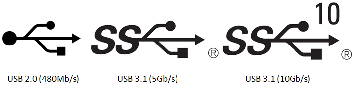
In the real world, your average user will pick a cable and will simply not be able to determine the capabilities of the cable by looking at it. Even if the cable has the appropriate logo to distinguish them, not every user will understand what the hieroglyphs mean.
Software, however, and Power Delivery may very well help with this. I've been looking very closely at the kernel's USB Type-C Connector Class.
The connector class creates the following structure in sysfs, populating these nodes with important properties queried from the cable, the USB-C port, and the port's partner:
/sys/class/typec/
/sys/class/typec/port0 <---------------------------Me
/sys/class/typec/port0/port0-partner/ <------------My Partner
/sys/class/typec/port0/port0-cable/ <--------------Our Cable
/sys/class/typec/port0/port0-cable/port0-plug0 <---Cable SOP'
/sys/class/typec/port0/port0-cable/port0-plug1 <---Cable SOP"
You may see where I'm going from here. Once user space is able to see what the cable and its e-marker chip has advertised, an App or Settings panel in the OS could tell the user what the cable is, and hopefully in clear language what the cable can do, even if the cable is unlabeled, or the user doesn't understand the obscure logos.
Lots of work remains here. The present Type-C Connector class needs to be synced with the latest version of the USB-C and PD spec, but this gives me hope that users will have a tool (any USB-C phone with PD) in their pocket to quickly identify cables.